by Nicholas Carlini 2020-04-01
This is the first in a series of posts ([2], [3], [4], [5]) implementing digital logic gates on top of Conway's game of life, with the final goal of designing an Intel 4004 and using it to simulate game of life. (The fact that I'm writing this first post on April 1 is mostly unintentional. Mostly.)
I'm going to start off this post by describing the first step in the process: creating standard basic digital logic gates (e.g., AND / OR / NOT gates) on top of Conway's Game of Life (a two-dimensional cellular automata).
(Why even do this? Mostly because it's possible, but also because I have something of a fixation with obscure Turing completeness---see, for example, some code I wrote that proves C's printf is Turing complete.)
As mentioned, my ultimate goal is to be able to “emulate” a full Intel 4004 (one of the worlds first mass-produced microprocessors) on top of the Game of Life. I'm setting myself a target frequency of 1Hz -- I want to be able to see the circuit run in real time. Faster of course would be better, but I don't want it to be much slower than that.
It's going to take a little while to get there, so I'm just going to start out this post with the basics: how the game of life works, and how to create some simple circuits on top of it. By the end, you'll see how to make simple circuits, like this adder below that computes the sum of six (0110) and five (0101) to get eleven (1011).
Game of Life Basics
As mentioned earlier, the Game of Life consists of an (infinite) grid where all cells at any given timestep are either alive or dead.
The rules are very simple. If a cell is alive at one timestep, it remains alive if two or three neighbors (determined as the four directly adjacent cells along with the four additional diagonally-adjacent cells) are alive; otherwise, it dies (as if by over-population). Conversely, if a cell is dead at some timestep, it becomes alive at the next timestep if exactly three of its neighbors are alive, otherwise it remains dead. These rules turn out to be exceptionally powerful.
Glider — This here is a glider. It very slowly ... glides ... to the south east of the grid. It is one of the simplest interesting shapes, going through four different transformations before returning to its original form one cell down and one cell right.
We say the glider moves with a speed of c/4: it takes four ticks of the grid state for the glider to move one cell down and to the right. The notation c refers to the equivalent to the speed of light: the fastest that any reaction can move is one cell per tick of the grid. The glider is four times slower than that.
(While we're here, let me briefly cover how to work the simulator at right. The simulation can be started and stopped by clicking on it. The buttons on the top can increase and decrease the simulation speed. If it's paused, you can advance one timestep forward at a time by clicking “tick”. This will be the same simulator you'll see throughout the rest of this page, so get used to it.)
I use the glider as the basic charge-carrying component in a circuit. If a glider is present, it means there is some charge flowing along that “wire”, if not, there is no charge.
Glider Gun — The next most useful component is called Gosper's Glider Gun Named after Bill Gospher, the Glider Gun was the first demonstration of a finite configuration of cells that produces an infinite number of cells if let run forever. . Every 30 steps, the glider gun emits a single glider which travels as just shown previously.
The glider gun is actually a fairly complex device, and not at all easy to understand at a very low level. Don't worry though, you can understand all of the rest of this page without really understanding why the glider gun works --- as long as you know that it's something magic that spits out gliders to the south east of the grid.
I will use glider guns extensively to create streams of gliders to better represent flow of electricity.
Eater — The final individual component I will use in the circuit construction is called an eater, so named because when a glider collides with it, the glider will be “eaten” while the eater will remain unharmed.
Despite being very simple, this is the first real example of an interaction between two components. It doesn't take much to cause a glider to die, but the eater is much more stable and will remain after many different types of collisions. The eater can actually cause many different types of gliders to die, but that's out of scope for this writeup.
Glider Collisions
In fact, the collision I created above between the glider and eater are just the first example of interactions between components. After understanding the basic components, understanding how gliders collide is the final necessary piece of background before understanding the circuit construction. I'll demonstrate three basic types of collisions that will be used throughout.
Notice the importance of synchronizing the two glider streams. Here, two gliders coming from the upper left glider gun escape because the gliders coming from the lower left gun are slightly further behind. We'll fix that in the next example.
By sticking these two guns very close to each other, we can therefore use this to create a period-60 gun that emits gliders once every 60 generations. This is going to be important later.
The reason why this collision works is because after the two gliders collide, they leave behind a 2x2 block. The next glider coming from the period-30 glider gun will hit this block and both will die, and then the cycle will repeat itself.
Wires and Gates
Wires are implemented as glider streams. The wire has a 1-bit along it when gliders are present and moving. If there are no gliders, it represents a 0-bit. The glider stream used for a 1-bit are always two periods of a glider gun, every 60 generations.
Constructing the adder above requires three “real” gates (AND, OR, and NOT gates), as well as three auxiliary gates which deal with glider-flow which are not required for actual wires (splitter, crossover, and rotation).
Each circuit is constructed entirely out of glider guns with the logic determined by different types of glider collision. In a future post I'm going to create better gates that require more complex types of interactions. But before I can do that, we'll need to start with the basics.
Each gate is 270 cells square. This value is completely arbitrary, other than that the edge length has to be a multiple of 30, because that is the period of a glider gun. It is important that the size be a multiple of the period so that even when gliders travel long distances and enter a new gate their phases will always align.
NOT Gate
This did what we wanted: there was no glider stream coming in, so there is a stream going out. However, the stream has been rotated by 90 degrees: if the stream previously was moving down to the right, now it's moving up and to the right. While it's possible to design a NOT gate that doesn't rotate the stream, it's somewhat more complicated. We'll leave that to later.
The input corresponds to stream (1) being present. Using a standard collision, this period-60 stream thins stream (2) from a period of 30 to 60. Instead of stream (3) always colliding with stream (2), now we allow stream (3) to pass one glider through stream (2) every 120 generations. The gliders that get passed continue along stream (3) until it collides with the output stream (4), and both are terminated. Just what we wanted.
AND Gate
There's an output stream (9) that would like to exit, but when there's no outside interaction, stream (8) causes it to be terminated before it's able to leave. Streams (3)-(7) don't have any impact yet, they're just idling waiting for some stream to come in from either the NW (1) or SW (2).
Notice that while the steady state is correct, a few gliders manage to slip through the output right after stream (1) arrives. This is not unlike in actual electronics where the steady state ends up correct, but there's a period of time when the voltage is dropping from high to low (or vice versa) where everything goes a bit crazy.
From this direction, there were no gates leaking out. The steady-state behaviour is correct throughout the entire run.
As in the first case, stream (1) collides with stream (4) and allows stream (3) to continue on. As in the second case, stream (2) collides with stream (5), thinning it to period 60 and allowing stream (6) to continue on.
But now it all comes together. Stream (6) now collides with stream (3), thinning (3) to period 60 in the process. Stream (3) now can pass through stream (7) unhindered, and when it contacts stream (8) will remove it entirely. This allows the output stream (9) to be sent out.
OR Gate
When neither (1) nor (2) are present, not a lot happens (as was the case with AND). Streams (3)-(8) just idle in place. Stream (9), which will become the output stream, collides with stream (10) stopping it from passing.
Notice here that there's nothing special that means the output stream has to start out period 60. After all, a period 60 gun is just created by two period 30 guns as we showed earlier.
While the previous case only required two collision interactions, this one required five in order to work: the reason it is slightly more involved is due to the required rotation by 90 degrees.
There's some “extra work” happening here, thinning the stream twice, but there's no harm in that. The end result is still the same.
Crossover
If this gate did not exist, then any time two streams crossed we would have a nasty explosion. And while there are some things that can be done with planar circuits, in even the simplest adders require that we be able to cross wires over each other.
This is a very simple gate. All we're going to do is slightly shift over stream 2 so that it misses colliding with stream (1). To do this, we make stream (2) collide with stream (3) thinning it. Stream (3) can now pass through stream (4). So stream (4) can continue. Stream (4) now crosses over stream (1), having no effect, and then colliding with stream (5), stopping it entirely. This allows the output stream (6) to continue on out. Therefore, it doesn't matter if stream (1) is present or not.
Rotator
The rotation gate takes a single input stream from NW (1) and outputs it to NE (4), rotating it by 90 degrees. When the input stream (1) is not present, stream (2) collides with stream (3) and stops it there. Output stream (4) collides with stream (5) and nothing happens.
The fact that we need to explicitly rotate glider streams is important for how we design circuits. It's just as expensive to rotate a glider stream as it is to, do meaningful operations (say, compute the NOT). This will come into play later.
(Now, while it's not strictly necessary, it's very convenient to also have a gate to rotate by 270 degrees, but it's entirely symmetric. I've skipped it here.)
Duplicator
Specifically, we take a stream from NW (1), duplicating it to both SE (6) and NE (4). When the input stream (1) is not present, stream (2) collides with stream (3) and cancels it out. The first output stream (4) then collides with stream (5) and does not go anywhere. The second output stream (6) also collides with stream (7) and does not go anywhere.
(Again, it's convenient to have a duplicate-but-rotate-by-270, which I implement don't show here.)
Creating the 4-bit adder
The final necessary step is to create the four bit adder circuit as shown above. The next post will be dedicated to circuit design using these gates, but as a short teaser, let's briefly talk about how to make a simple adder.
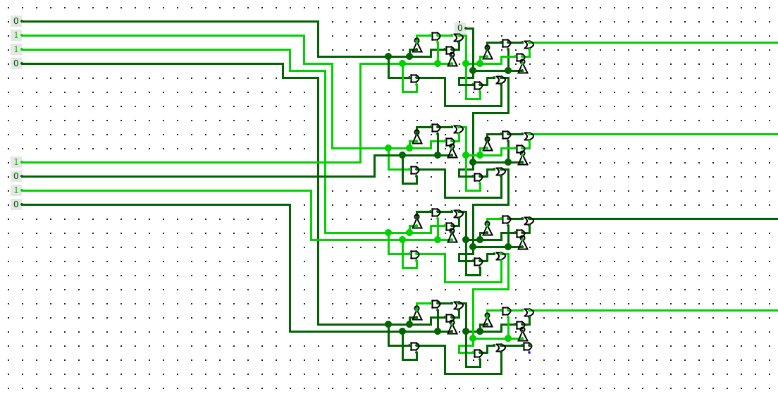
To design the circuits I used logisim, a digital logic simulator, and then wrote a “compiler” of sorts that reads the saved circuit XML file and determines where each of the above gates should be added.
The circuit itself is a standard ripple carry adder implemented in the naive way. Each full adder is thirteen gates, and I could definitely have done fewer, but if I did there wouldn't be anything left to talk about next time ... so don't worry, we'll get there.
I use golly to simulate game of life efficiently. That's a whole topic of its own, something I'm not going to get into here, except to say that hashlife is really an amazing algorithm you should study. The adder shown at the top is just a replay of a golly run, instead of actually running the game of life itself like is done in the other diagrams. If you want to download the adder circuit to look at in golly, it's available here.
Next time, I'll cover how to use these primitives to design useful circuits on top of the game of life. There are a number of interesting differences between designing circuits on top of game of life and designing circuits built on actual physics. We'll make use of some of these in order to design an efficient seven segment display that's hooked up to a clocked circult to count.
There's also an RSS Feed if that's more of your thing.